2. ROS 2 and Kubernetes
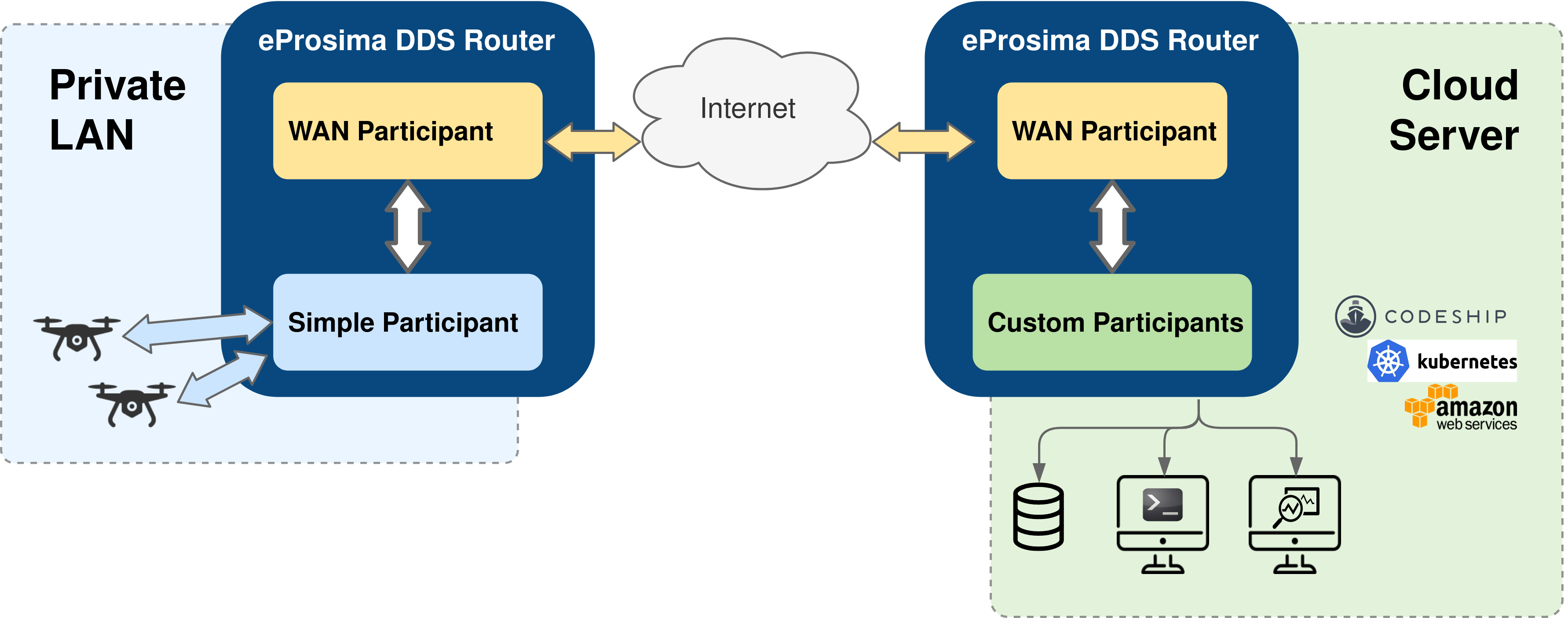
Apart from plain LAN-to-LAN communication, Cloud environments such as container-oriented platforms have also been present throughout the DDS Router design phase. In this walk-through example, we will set up both a Kubernetes (K8s) network and a local environment in order to establish communication between a pair of ROS nodes, one sending messages from a LAN (talker) and another one (listener) receiving them in the Cloud. This will be accomplished by having a DDS Router instance at each side of the communication.
2.1. Local setup
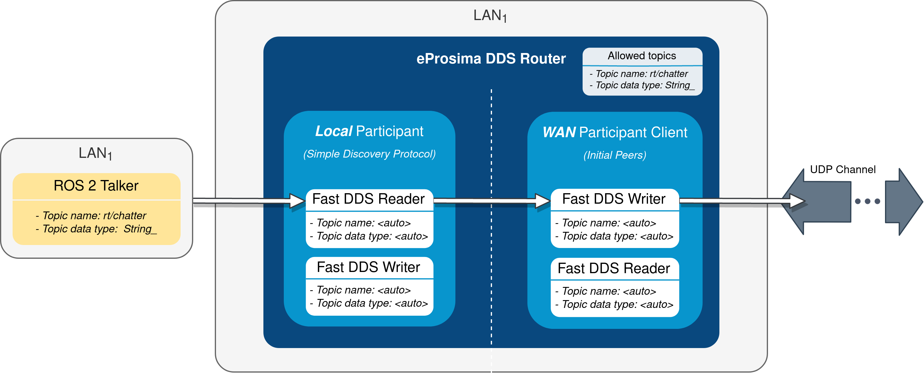
The local instance of DDS Router (local router) only requires to have a Simple Participant, and a WAN Participant that will play the client role in the discovery process of remote participants (see Initial Peers discovery mechanism).
After having acknowledged each other’s existence through Simple DDS discovery mechanism (multicast communication), the local participant will start receiving messages published by the ROS 2 talker node, and will then forward them to the WAN participant. Following, these messages will be sent to another participant hosted on a K8s cluster to which it connects via WAN communication over UDP/IP.
Following is a representation of the above-described scenario:
2.1.1. Local router
The configuration file used by the local router will be the following:
# local-ddsrouter.yaml

allowlist:
  - name: rt/chatter
    type: std_msgs::msg::dds_::String_

participants:

  - name: SimpleParticipant
    kind: local
    domain: 0

  - name: LocalWAN
    kind: wan
    listening-addresses:      # Needed for UDP communication
      - ip: 3.3.3.3           # LAN public IP
        port: 30003
        transport: udp
    connection-addresses:
      - ip: 2.2.2.2           # Public IP exposed by the k8s cluster to reach the cloud DDS-Router
        port: 30002
        transport: udp
Note that the simple participant will be receiving messages sent in DDS domain 0. Also note that, due to the choice
of UDP as transport protocol, a listening address with the LAN public IP address needs to be specified for the local WAN
participant, even when behaving as client in the participant discovery process. Make sure that the given port is
reachable from outside this local network by properly configuring port forwarding in your Internet router device.
The connection address points to the remote WAN participant deployed in the K8s cluster. For further details on how to
configure WAN communication, please have a look at WAN Configuration and
WAN Participant Configuration Example.
Note
As an alternative, TCP transport may be used instead of UDP. This has the advantage of not requiring to set a listening address in the local router’s WAN participant (TCP client), so there is no need to fiddle with the configuration of your Internet router device.
To launch the local router, execute:
ddsrouter --config-path local-ddsrouter.yaml
2.1.2. Talker
This example will make use of ROS 2 galactic with demo-nodes-cpp package installed. If not already present in your
system, you may choose any of the available options to install ROS galactic,
or even consider directly using a distributed Docker image. Just make sure the
resulting environment is prepared to utilize eProsima Fast DDS as middleware (see Working with eProsima Fast DDS).
Once ROS 2 is installed, start publishing messages in DDS domain 0 by executing:
RMW_IMPLEMENTATION=rmw_fastrtps_cpp ros2 run demo_nodes_cpp talker
2.2. Kubernetes setup
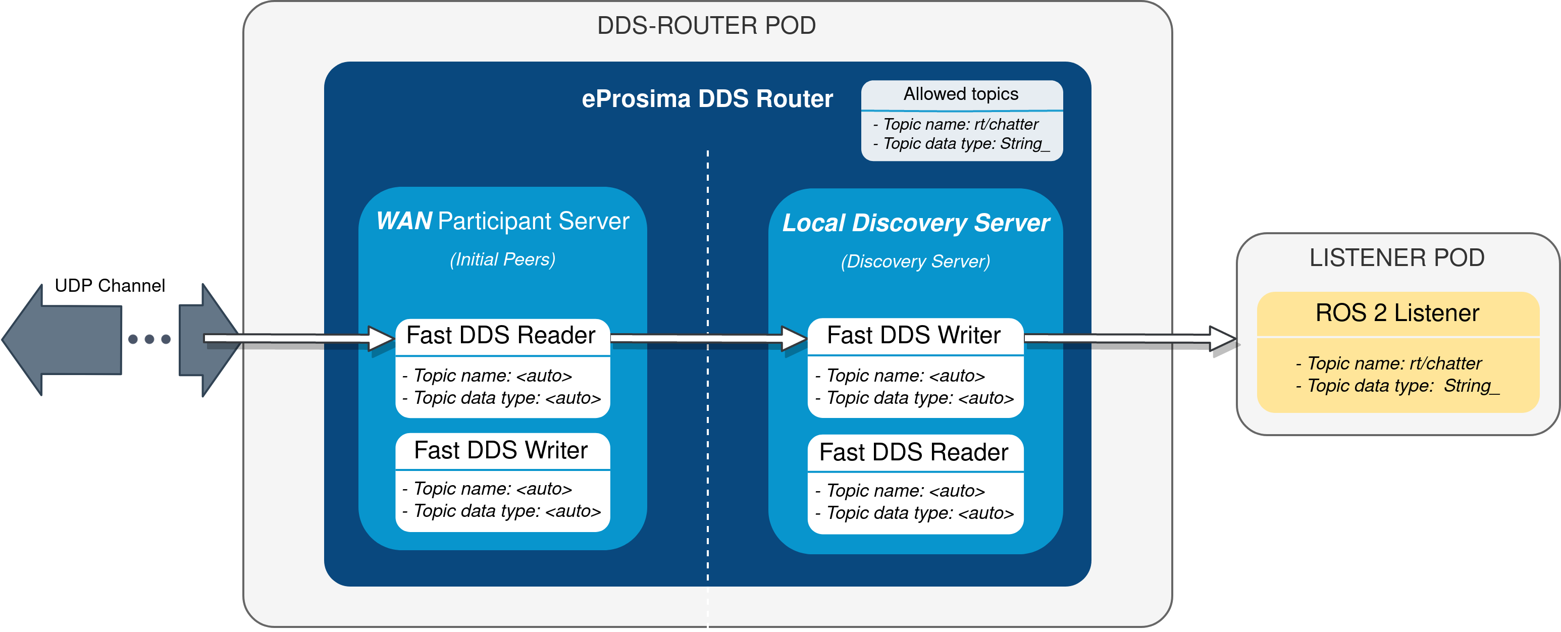
Two different deployments will be used for this example, each in a different K8s pod. The DDS Router cloud instance (cloud router) consists of two participants:
A WAN Participant that receives the messages coming from our LAN through the aforementioned UDP communication channel.
A Local Discovery Server (local DS) that propagates them to a ROS 2 listener node hosted in a different K8s pod.
The choice of a Local Discovery Server instead of a Simple Participant to communicate with the listener has to do with the difficulty of enabling multicast routing in cloud environments.
The described scheme is represented in the following figure:
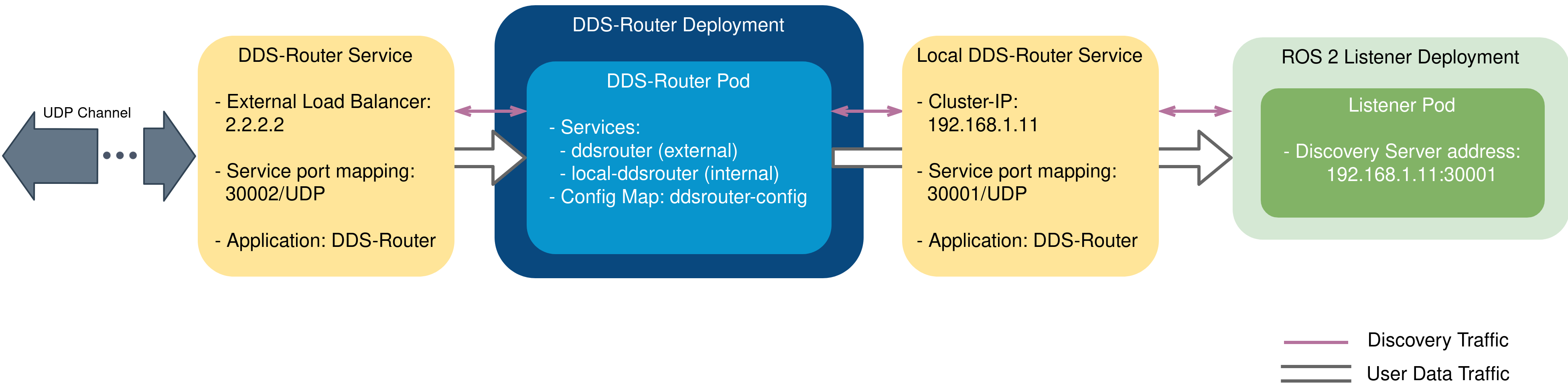
In addition to the two mentioned deployments, two K8s services are required in order to direct dataflow to each of the pods. A LoadBalancer will forward messages reaching the cluster to the WAN participant of the cloud router, and a ClusterIP service will be in charge of delivering messages from the local DS to the listener pod. Following are the settings needed to launch these services in K8s:
kind: Service
apiVersion: v1
metadata:
  name: ddsrouter
  labels:
    app: ddsrouter
spec:
  ports:
    - name: UDP-30002
      protocol: UDP
      port: 30002
      targetPort: 30002
  selector:
    app: ddsrouter
  type: LoadBalancer
kind: Service
apiVersion: v1
metadata:
  name: local-ddsrouter
spec:
  ports:
    - name: UDP-30001
      protocol: UDP
      port: 30001
      targetPort: 30001
  selector:
    app: ddsrouter
  clusterIP: 192.168.1.11  # Private IP only reachable within the k8s cluster to communicate with the ddsrouter application
  type: ClusterIP
Note
An Ingress needs to be configured for the
LoadBalancer service to make it externally-reachable. In this example we consider the assigned public IP address to
be 2.2.2.2.
The configuration file used for the cloud router will be provided by setting up a ConfigMap:
kind: ConfigMap
apiVersion: v1
metadata:
  name: ddsrouter-config
data:
  ddsrouter.config.file: |-
    version: v5.0

    allowlist:
      - name: rt/chatter
        type: std_msgs::msg::dds_::String_

    participants:

      - name: LocalDiscoveryServer
        kind: local-discovery-server
        discovery-server-guid:
          ros-discovery-server: true
          id: 1
        listening-addresses:
          - ip: 192.168.1.11      # Private IP only reachable within the k8s cluster to communicate with the ddsrouter application
            port: 30001
            transport: udp

      - name: CloudWAN
        kind: wan
        listening-addresses:
          - ip: 2.2.2.2           # Public IP exposed by the k8s cluster to reach the cloud DDS-Router
            port: 30002
            transport: udp
Following is a representation of the overall K8s cluster configuration:
2.2.1. DDS-Router deployment
The cloud router is launched from within a Docker image, which uses as configuration file the one hosted in
the previously set up ConfigMap. This Docker image needs to be built and made available to the K8s cluster for using
DDS Router, which can be accomplished by providing the following
Dockerfile. If willing to see log messages in
STDOUT, use Dockerfile instead.
Assuming the name of the generated Docker image is ddsrouter:v3.5.1, the cloud router will then be deployed with the
following settings:
kind: Deployment
apiVersion: apps/v1
metadata:
  name: ddsrouter
  labels:
    app: ddsrouter
spec:
  replicas: 1
  selector:
    matchLabels:
      app: ddsrouter
  template:
    metadata:
      labels:
        app: ddsrouter
    spec:
      volumes:
        - name: config
          configMap:
            name: ddsrouter-config
            items:
              - key: ddsrouter.config.file
                path: DDSROUTER_CONFIGURATION.yaml
      containers:
        - name: ddsrouter
          image: ddsrouter:main
          ports:
            - containerPort: 30001
              protocol: UDP
            - containerPort: 30002
              protocol: UDP
          volumeMounts:
            - name: config
              mountPath: /ddsrouter/resources
      restartPolicy: Always
2.2.2. Listener deployment
A suitable Docker image must also be provided in the context of the cluster in order to use ROS 2. We will use
ros:galactic as basis for this image, install demo-nodes-cpp, and include a parser that will allow us to specify
the port and IP address of the local DS. This can be achieved by using the following Dockerfile and entrypoint:
FROM ros:galactic

SHELL ["/bin/bash", "-c"]

# Install demo-nodes-cpp
RUN source /opt/ros/$ROS_DISTRO/setup.bash && \
    apt update && \
    apt install -y ros-$ROS_DISTRO-rmw-fastrtps-cpp && \
    apt install -y ros-$ROS_DISTRO-demo-nodes-cpp

# Set Fast DDS as middleware
ENV RMW_IMPLEMENTATION=rmw_fastrtps_cpp

COPY ./run.bash /
RUN chmod +x /run.bash

# Setup entrypoint
ENTRYPOINT ["/run.bash"]
#!/bin/bash

if [[ $1 == "listener" ]]
then
    NODE="listener"
else
    NODE="talker"
fi

SERVER_IP=$2
SERVER_PORT=$3

# Setup environment
source "/opt/ros/$ROS_DISTRO/setup.bash"

echo "Starting ${NODE} as client of Discovery Server ${SERVER_IP}:${SERVER_PORT}"
ROS_DISCOVERY_SERVER=";${SERVER_IP}:${SERVER_PORT}" ros2 run demo_nodes_cpp ${NODE}
Now, assuming the name of the built image is ros2-demo-nodes:galactic, the listener pod can be deployed by providing
the following configuration:
kind: Deployment
apiVersion: apps/v1
metadata:
  name: ros2-galactic-listener
  labels:
    app: ros2-galactic-listener
spec:
  replicas: 1
  selector:
    matchLabels:
      app: ros2-galactic-listener
  template:
    metadata:
      labels:
        app: ros2-galactic-listener
    spec:
      containers:
        - name: ros2-demo-nodes
          image: ros2-demo-nodes:galactic
          args:
            - listener
            - 192.168.1.11
            - '30001'
      restartPolicy: Always
Once all these components are up and running, communication should have been established between talker and listener
nodes, so that messages finally manage to reach the listener pod and get printed in its STDOUT.
Feel free to interchange the locations of the ROS nodes by slightly modifying the provided configuration files, hosting the talker in the K8s cluster while the listener runs in our LAN.